What is PWM "Dead Band"?

What is DEADBAND? What does DEADBAND mean? DEADBAND meaning, definition & explanation
| Topics covered in this article: |
| Ⅰ. What is a dead band? |
| Ⅱ. PWM dead band in DSP |
| Ⅲ. PWM related concepts |
Pulse width modulation (PWM) is the abbreviation for pulse width modulation. Rectification and inverters are the most widely utilized in power electronics. A rectifier bridge and an inverter bridge are required for this. Three bridge arms are required for three-phase power.
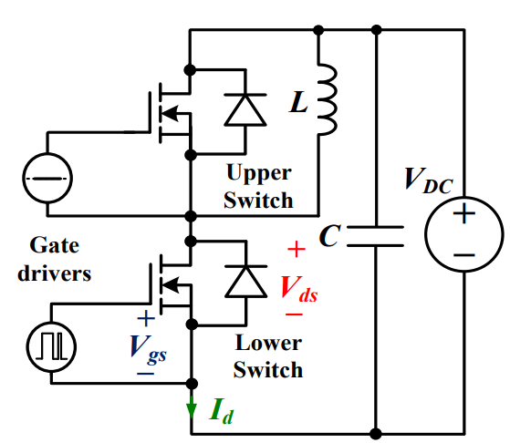
Taking two levels as an example, there are two power electronic devices, such as IGBTs, on each bridge arm. A short circuit will result if the two IGBTs are turned on at the same time.
As a result, by using a PWM wave with dead time, the upper and lower devices will not turn on at the same time. That is, if one device is switched on and then turned off, the other can be turned on after a period of inactivity.
Ⅰ. What is a dead band?
H-bridges or 3-phase bridges made out of high-power tubes, IGBTs, and other components are commonly used in high-power motors, frequency converters, and other applications.
Each bridge's upper and lower half bridges can never be turned on at the same time, but when the high-speed PWM drive signal reaches the control pole of the power element, it frequently has a delay effect for various reasons, causing one of the half-bridge components to not turn off when it should, causing the power components to burn out.
To avoid burning the power components, the dead band occurs when the upper half bridge is turned off and the lower half bridge is switched on after a period of time, or when the upper half bridge is turned on after a period of time after the lower half bridge is turned off. The dead band is the time when there is a delay. (That is, the upper and lower half bridge components are turned off.) Dead time control is not available in PWMs equipped with low-end single-chip microcomputers.
When the PWM is output, a protection period is established to prevent the upper and lower tubes of an H-bridge or half H-bridge from going on at the same time due to a switching speed problem. As a result, the upper and lower tubes will not have output at this time. Obviously. The waveform output will be stopped, but the dead time will only be a small percentage of the cycle.
The dead band will affect the output ripple, but it should not play a crucial role, because the PWM wave itself has a tiny duty cycle and the vacant part is greater than the dead band.
Ⅱ. PWM dead band in DSP
The upper and lower bridges of the same phase cannot be turned on at the same time during the rectification and inversion process, or the power supply will be short-circuited. In theory, the DSP's PWM won't switch on at the same moment, but the device's purpose is to prevent the PWM from being an immediate level jump. It always falls in a trapezoidal shape, through which the higher and lower bridges may pass. As a result, the higher and lower bridges are closed for a brief time and then selectively turned on to avoid direct connection of the upper and lower bridges. The dead band will cause the control performance to alter in real-time control. Difference.
The upper and lower bridge arms of the PWM's upper and lower bridge arms cannot be turned on at the same time. If both ends of the power supply are turned on at the same moment, a short circuit will occur. As a result, the two triggering signals must disconnect the triode when a certain amount of time has passed. The "dead band" is the name given to this location.
The average voltage output to the DC motor is determined by the duty cycle of the PWM; the PWM does not regulate the current.
PWM stands for pulse width modulation, which is the process of adjusting the time ratio between square wave high and low levels. A 20% duty cycle waveform will have 20% high level time and 80% low level time, while a 20% duty cycle waveform will have 20% high level time and 80% low level time. There is 60% high level time and 40% low level time in the waveform with a 60% duty cycle. The higher the output pulse amplitude, that is, the higher the voltage, the higher the duty cycle and the longer the high level period.
If the duty cycle is 0%, the high time is also 0%, and no voltage is output.
When the duty cycle is set to 100%, the entire voltage is output.
Therefore, by adjusting the duty cycle, the purpose of adjusting the output voltage can be achieved, and the output voltage can be continuously adjusted steplessly.
Ⅲ. PWM related concepts
1. Duty cycle
It is the ratio of the time the high level in the output PWM is maintained to the time of the PWM's clock cycle.
For example, if a PWM's frequency is 1000Hz, its clock cycle is 1ms, or 1000us. If the high level appears for 200us, then the low level must show for 800us, resulting in a duty cycle of 200:1000, or a duty ratio of 1:5.
2. Resolution
In other words, the minimum duty cycle can be met. For example, the theoretical resolution of 8-bit PWM is 1:255 (single slope), whereas the theoretical resolution of 16-bit PWM is 1:65535 (single slope) (single slope).
This is how often it happens. The resolution of 16-bit PWM. for example is 1:65535. T/C must be counted from 0 to 65535 to reach this resolution. Counting from 0 to 80 begins at 0..... Then its minimum resolution is 1:80, but it is also quicker, implying a higher PWM output frequency.
3. Double slope / single slope
Consider a PWM that counts from 0 to 80 and then back to 0 to 80... There is only one slope here.
Consider a PWM that counts from 0 to 80, then back to 0... This is a double incline.
The counting time of the double slope is doubled, resulting in a half-slower output PWM frequency, but the resolution is 1: (80+80)=1:160, which is doubled.
Assuming that the PWM is a single slope, set the highest count to 80 and a comparison value of 10, then when T/C counts from 0 to 10 (the counter continues to count up until it reaches the set value of 80), the microcontroller will control whether a specific IO port outputs 1 or 0 or is reversed according to your settings. It is the most fundamental principle of PWM in this fashion.
1. What does dead time mean?
Dead time is a protection period set to prevent the upper and lower tubes of the H-bridge or half-H-bridge from being turned on at the same time due to the switching speed problem when the PWM is output. Usually also refers to pwm response time. Since power devices such as IGBT (insulated gate power transistor) have a certain junction capacitance, it will cause a delay in turn-on and turn-off of the device.
2. How to set the time of pwm dead interval?
Choose according to your main circuit power tube.
Generally, the model of the power tube of the upper arm and the lower arm is the same. It is only necessary to check how much the off time of this type of tube is longer than the on time, and set the dead time to at least how much.
3. Why can't I see the dead zone of PWM with an oscilloscope?
The register that sets the dead zone is also DBTCONA, and the most common problem is that the waveform is not magnified enough, so the dead zone cannot be seen.
 Discovering New and Advanced Methodology for Determining the Dynamic Characterization of Wide Bandgap DevicesSaumitra Jagdale15 March 20242346
For a long era, silicon has stood out as the primary material for fabricating electronic devices due to its affordability, moderate efficiency, and performance capabilities. Despite its widespread use, silicon faces several limitations that render it unsuitable for applications involving high power and elevated temperatures. As technological advancements continue and the industry demands enhanced efficiency from devices, these limitations become increasingly vivid. In the quest for electronic devices that are more potent, efficient, and compact, wide bandgap materials are emerging as a dominant player. Their superiority over silicon in crucial aspects such as efficiency, higher junction temperatures, power density, thinner drift regions, and faster switching speeds positions them as the preferred materials for the future of power electronics.
Read More A Comprehensive Guide to FPGA Development BoardsUTMEL11 September 20257956
This comprehensive guide will take you on a journey through the fascinating world of FPGA development boards. We’ll explore what they are, how they differ from microcontrollers, and most importantly, how to choose the perfect board for your needs. Whether you’re a seasoned engineer or a curious hobbyist, prepare to unlock new possibilities in hardware design and accelerate your projects. We’ll cover everything from budget-friendly options to specialized boards for image processing, delve into popular learning paths, and even provide insights into essential software like Vivado. By the end of this article, you’ll have a clear roadmap to navigate the FPGA landscape and make informed decisions for your next groundbreaking endeavor.
Read More Applications of FPGAs in Artificial Intelligence: A Comprehensive GuideUTMEL29 August 20252196
This comprehensive guide explores FPGAs as powerful AI accelerators that offer distinct advantages over traditional GPUs and CPUs. FPGAs provide reconfigurable hardware that can be customized for specific AI workloads, delivering superior energy efficiency, ultra-low latency, and deterministic performance—particularly valuable for edge AI applications. While GPUs excel at parallel processing for training, FPGAs shine in inference tasks through their adaptability and power optimization. The document covers practical implementation challenges, including development complexity and resource constraints, while highlighting solutions like High-Level Synthesis tools and vendor-specific AI development suites from Intel and AMD/Xilinx. Real-world applications span telecommunications, healthcare, autonomous vehicles, and financial services, demonstrating FPGAs' versatility in mission-critical systems requiring real-time processing and minimal power consumption.
Read More 800G Optical Transceivers: The Guide for AI Data CentersUTMEL24 December 20251026
The complete guide to 800G Optical Transceiver standards (QSFP-DD vs. OSFP). Overcome supply shortages and scale your AI data center with Utmel Electronic.
Read More Xilinx FPGAs: From Getting Started to Advanced Application DevelopmentUTMEL09 September 20252883
This guide is your comprehensive roadmap to understanding and mastering the world of Xilinx FPGA technology. From selecting your first board to deploying advanced AI applications, we'll cover everything you need to know to unlock the potential of these remarkable devices. The global FPGA market is on a significant growth trajectory, expected to expand from USD 8.37 billion in 2025 to USD 17.53 billion by 2035. This surge is fueled by the relentless demand for high-performance, adaptable computing in everything from 5G networks and data centers to autonomous vehicles and the Internet of Things (IoT). This guide will walk you through the key concepts, tools, and products in the Xilinx ecosystem, ensuring you're well-equipped to be a part of this technological revolution.
Read More
Subscribe to Utmel !
![AD5520JSTZ]() AD5520JSTZ
AD5520JSTZAnalog Devices Inc.
![FOD3184SDV]() FOD3184SDV
FOD3184SDVON Semiconductor
![AT88SC0808CA-SH]() AT88SC0808CA-SH
AT88SC0808CA-SHMicrochip Technology
![AT88SC0204CA-SU]() AT88SC0204CA-SU
AT88SC0204CA-SUMicrochip Technology
![HCS200/SN]() HCS200/SN
HCS200/SNMicrochip Technology
![ACPL-332J-500E]() ACPL-332J-500E
ACPL-332J-500EBroadcom Limited
![FOD8320R2]() FOD8320R2
FOD8320R2ON Semiconductor
![ATECC108A-SSHCZ-B]() ATECC108A-SSHCZ-B
ATECC108A-SSHCZ-BMicrochip Technology
![HCS512-I/P]() HCS512-I/P
HCS512-I/PMicrochip Technology
![PAM8904JER]() PAM8904JER
PAM8904JERDiodes Incorporated


